CAD Suspension Bracket Project
- Alex Harrington
- May 18, 2016
- 2 min read
In the CAD/CAM module we have been designing a suspension bracket that will be designed in solidworks and then machined out on the CNC machine at university.
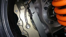
My part is a simple design inspired by an example that used to be on a Mclaren Formula 1 car. This was a good place to start because in Formula 1 only the best parts are used for the job, the only constraint that I has was that the Formula 1 bracket is made from titanium which is an extremely good metal as it is very strong but is also very expensive. The part I will be making will be CNC machined out of a block/billet of aluminium this will not be used on a car that is why it can be made from a cheaper weaker material.
The designing of the part as mentioned was done in solidworks, I made use of a lot of different tools in the program such as the chamfers and fillet tools unit I decided on my final design as pictured below. The CNC machine used will not be able to give a solid edge on the inside of the part as pictured but instead a radius will be put on the part as to maintain the strengthening qualities this edge was designed for and the machine is capable of doing this easily therefore the design will be changed slightly because of the constraints of the machine.
The actual machining part has started to be programmed in by myself with the help of an experienced technician. When the CNC machine being used has a built in simulation option, in which it shows the simulation on the screen of the commands that has been entered into it, this is very useful as when we initially put in the commands the machine was going to cut on the wrong side of the shape, with a simple selection on the machine though it was fixed and the simulation run again showing no issues with the commands.


Comments